[2016 version upgraded in February 2019]
Doug-Nash 5-Speed Manual – PDF
[Liberty now makes new gears for the Doug-Nash]
Tech Tips – Updated October 10, 2021

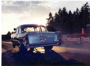
We love this shot that Mike Gardner took on our 3rd round bye with the front parking lights lit. We love the new grille and the now functional parking lights! Thanks Mike for the memories!
![]()
Internal shortcuts – Recommend you read complete series if this is your first visit:
Introduction – Jan 04 Reading Sparkplugs – Jan 04 – Updated 7 June 07
Reading Exhaust Valves & Ports – Feb 04
Air Density & Fuel Mixtures – Feb 04 – Updated 16 July 12
Why Adjustable Headers are Important – Feb 04 – Updated 28 Dec 06
Carb Spacers & Cam Timing – Feb 04
The Great Balancing Act & Flow Bench Fallacies – Feb 04 – Updated Nov 08
Centrifugal Advance Curve & Lighting the Spark – Feb 04
Curing the Carburetor Hesitation & Fuel Starvation on Launch – Mar 04 – Updated Aug 05
Fuel Supply – Apr 04 – Updated May 04
High-RPM Misfire – Suggested MSD Updates – Aug 04 – Updated: May 05 – Updated: August 06
Important Assembly Tips – Degreeing your cam, valve guide & pushrod clearance, etc – Feb 05 – Updated Feb 06
Pro Stock Staging & Leave by Jeg Coughlin, Jr. – Feb 05
Rod Length Discussion by Stahl Headers – Aug 05
Holley 750 main body upgrade – Feb 06
Holley Nitrous Oxide Technical Article – May 06
Chassis Basics – Updated, Jan 08
Breaking the Big MPH Myth – Sep 06
The A, B, C’s of EGT’s and Oxygen Sensors by Pro Systems Carburetors – Posted Feb 08
Quench Quest: Squish, Quench, and Piston-to-Head Clearance By Jeff Smith – Posted Apr 08
CFM Head Flow Discussion – Posted Oct & Nov 08
Dominator Air Bleeds – Courtesy of Holley®, – Posted Nov 09
Wider 2nd Ring End Gaps Recommended – Dec 09
Oil Pump Volume and Pressure Explanation – by Melling Engine Parts – Dec 09
Are Burnouts Abusing Your Engine? by David Reher – Dec 10
Debunking Aluminum Rod Myths With GRP – Oct 2011
Testing Lunati Cams – 4/7 Swap Cam Test – Posted Jan 2012
Melling Oil Pump Relief Springs – Posted Aug 2012
Isky “EZ” Roller Lifters – Posted Sept 2012
Are your valve springs and pushrods ready for next season? – Posted April 2013
Camshaft 101 – An excellent article regarding camshafts – Posted December 2014
Electronic Diagnostics by Roger Young – Posted January 2016
MSD Troubleshooting – Posted July 2015
Break-in Oil – Posted February 2016
Bosch Relay Wiring – Posted April 2016
David Reher: Oil Is Everything – Posted September 2016
ELITE Training Video: Don’t Let Your Head Get in the Way! – Posted April 11, 2017
Lengthy discussion, instructions & video on our new Ram clutch for 2018 – Posted August 1, 2017
“Controlling the supply of oil in the shutdown area should be a top priority.” by David Reher, Reher-Morrison Racing Engines – Posted October 2017
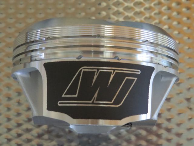
What Is A Strutted Piston – Wiseco Automotive – March 2018
Track Safety: Questions You Need to Ask – August 2018
Standard Ring Tension Is A Myth – Wiseco Pistons – October 2018
Pedal ratio calculator, Gear ratio and RPM calculator, Tire size calculator courtesy of Mark Williams Enterprises, Inc. – January 2019
Long Style Clutch Building and Design by Cale Aronson – March 21, 2019
How to pick valve springs for your race car – NHRA – May 10, 2019
Pretty good article. It has been my personal experience that many of the valve springs that come in a cam kit are too light for high RPM engines with mechanical roller cams. We’re having good luck with the PacAloy springs in our engines – Roger Young
Black Magic Clutches – Interactive Clutch Tuning Podcast with Cale Aronson – April 23, 2020
The Importance Of Clutch Break In Explained – Ram Clutches – Oct 29, 2020
Aluminum or Steel Flywheel? – Ram Clutches – October 10, 2021
Questions? Comments? About the Author
![]()
Introduction – 29 Jan 04:
Disclaimer: We offer you these articles for your consideration, and we accept NO legal responsibility. You must accept any and all responsibilty for your engine, vehicle & safety!
 Here I’ll be providing information on reading sparkplugs for maximum performance, how atmospheric changes impact jetting, discuss header lengths and other tuning “secrets.” Why? Because it has been our experience in helping some of our fellow racers that many are misinformed when it comes to tuning their engines for maximum performance.
A case in point: One friend with a big-block Chev a few years ago went out and spent a bundle for some excellent heads. After all the promises, big bucks and hard work, he didn’t pick up even a tenth. Understandably, he was very disappointed & frustrated. His next step was to go out and purchase the latest and greatest new roller-cam profiles and slowed down even more. He then had the intake worked on and things only got worse. At this point he was ready to throw those very expensive heads in the trash and sell his ride!
Was it the new heads? No, his tuning combination was wrong (and had always been wrong in my opinion), and he also didn’t realize with higher-flow heads that the engine would lose lower-end torque when operating at the same rpm range of his old heads.
After we “read” his sparkplugs (which must be done after clicking the engine at the end of the 1/4-mile under full-load conditions), and after much arm twisting (others had convinced him that his tune-up was “right on” and to make our suggested changes would result in immediate catastrophic destruction), we finally got him to advance his ignition timing, lower the octane of fuel he was using to be compatible with the compression-ratio he is running, make a spark plug heat range change and he instantly picked up four-tenths and four mph with no engine damage and it cost him very little. In fact, his engine is much more reliable today then when he was running slower with the improper tune-up, which is what we have learned over the years – that with good pieces in the engine, it will show less engine wear when running at peak efficiency!
A gearing change to twist his engine a bit harder to work in the rpm range with his new heads netted him additional further increases, but the main performance increases came from making some small, carefully monitored, and inexpensive adjustments in his tune-up. [This engine finally met its demise years later in a different vehicle when the oil pump pickup fractured and starved the engine for oil].
So, before you decide to read anything into the example above, advance your timing 10 degrees, run hotter plugs with projected tips, switch to regular-unleaded fuel and detonate your engine to death, please be patient and we’ll try to provide you with a few thought-provoking articles in the future! I’ve put them here on a separate page to make it more user-friendly.
For many, building your own engine seems to be a lost art form with the availability and costs of some excellent crate motors, but learning to tune them doesn’t need to be.
I’m not going to attempt to reinvent the wheel, so where I can find excellent articles that I agree with, I’ll steer you that direction! If you need help, drop me an email with “tech tips” in the subject line!
![]()
January edition – Reading sparkplugs:
Spark Plug Reading 101 by Mike Canter – courtesy of Dragstuff.com
Comment: Our timing is correct for maximum power with our engines when the “blue line” Mike discusses, appears just above the weld on the ground electrode with the proper plug heat range & fuel mixture.(1)
Another related plug reading article by Meaux Racing Heads (with excellent pictures) states that the location of the “blue line” indicates if the heat range is correct – that is true but not the full story – and should be used as a base-line in chosing the proper heat range.
Please note, as you advance the timing the blue line will move towards the direction of the weld on the ground electrode, and towards the tip as timing is retarded (timing changes the heat in the combustion chamber as does mixture & engine coolant temp – therefore moving the location of the blue line).
To play it safe, it is better to run too “cold” of racing plug and increase the heat range one step at a time as necessary. Same for jetting; start out a little rich and go leaner as required. With most Chev engines using racing fuel without nitrous start out about 36 degrees (at full advance) and slowly advance the timing as required. If your MPH suffers, retard the timing! MAKE ONLY ONE SLIGHT CHANGE AT A TIME – and remember it will take several full passes to “read” the plugs after making that one change!
Another rule of thumb but there is always exceptions; the larger the displacement, the less ignition lead or total timing required.
As Mike notes, you can only properly read your plugs when clicking the engine at end of the traps!! – which reportedly can be harmful to the planet gears in an automatic transmission!
![]() June ’05: Also it must be noted that different fuels with the same tune-up and plug will change the color on the plug insulator. With one fuel the insulator will be bone white – with another the color of the insulator will match closely with the color of the exhaust valve. Conclusion: Concentrate on the base ring and the blue line!
June ’05: Also it must be noted that different fuels with the same tune-up and plug will change the color on the plug insulator. With one fuel the insulator will be bone white – with another the color of the insulator will match closely with the color of the exhaust valve. Conclusion: Concentrate on the base ring and the blue line!
(1) In coming discussions, I’ll explain why reading the exhaust valves & exhaust ports handshakes with the plug readings & fuel mixtures. Stay tuned!
![]()
February edition – Reading the exhaust valve:
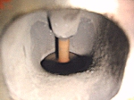
If your fuel mixture is correct, the valve should have a carmel appearance and the color of the exhaust port should be very close to the color of the ‘base ring’ on your sparkplug. If the exhaust valve is white or shows no color after several passes, you’re too lean – black, you’re too rich!
Read the exhaust valves in conjunction with your plug readings. Changing your header length and/or primary tube diameter, intake manifold changes, cam profiles or cam timing will impact your mixture readings even with the same jetting & timing settings. Also remember, if you change cam timing, you are also changing the ignition timing with a distributor trigger. Re-check your ignition timing after advancing or retarding the camshaft.
Again, make one small change at a time, keep records of your changes, and read your plugs and exhaust ports after each change. Reading all the plugs & exhaust ports can indicate if one or more cylinders are running leaner or richer than others – which is not uncommon – and can often be balanced by just changing one jet in one corner of your carburetor feeding those cylinders. Stay tuned!
A WORD ON THERMOCOUPLES/EGT [for judging fuel mixtures]
“With the cooperation of a ProStock engine builder/crew chief, we were able to prove in 1992 that thermocouples placed in headers are not a valid source of EGT info. They must be positioned in spacer blocks between the cylinder head and headers.” – Stahl Headers, Inc. – Oct ’93 newsletter
A WORD ON OXYGEN SENSORS FOR
JUDGING FUEL MIXTURES
Some are attempting to use oxygen sensors in their exhaust to judge wide-open-throttle (WOT) air/fuel mixtures. This is a waste of time and expense. Computer-controlled vehicles use the O2 sensor to provide feedback and adjustments to the mixture settings under relatively light-load conditions. Under heavy loads, the O2 sensor is taken out of the loop in computer systems and the fuel mixture is enriched by input from a mass airflow sensor (MAF) or manifold absolute pressure (MAP) sensor (along with other inputs) and as programmed by the prom in the ECM.
Simply put, if you are attempting to adjust main jetting with readings gathered from an O2 sensor for racing, the end result will be an extremely lean air/fuel mixture and extensive engine damage!
To my knowledge, there is only one oxygen sensor data retrieval system which uses a wide-band five-wire oxgen sensor specifically designed with a wide enough range to be used for racing applications. – Roger Young, Edwards & Young – Feb 04
IGNITION TIMING vs DYNO SETTINGS
“A short track will normally want two degrees more timing than the optimum timing derived on the dyno. The engine is always a little ‘quicker.’ Some drag race engines want four or five degrees more.” – Stahl Headers, Inc. – Sept ’87 newsletter
JETTING vs DYNO SETTINGS
“The difference between the optimum jetting with a carburetor engine on the dyno and the race track varies with the size of the track. The shorter the track, the quicker the engine accelerates [such as in drag racing] and the more fuel lag there is, thus requiring jets 4 or 5 numbers larger than the dyno wants. A very large track may only want 1 or 2 numbers larger. These thoughts apply ONLY to gasoline. Methanol creates a different situation.” – Stahl Headers, Inc. – Sept ’87 newsletter.
![]()
February edition – Air Density & Fuel Mixtures:
Preface: There is much yet to cover in engine tuning but I want to tackle this subject at this time because it is one that can help many once you have your air/fuel mixture and timing close. Also, with spring coming up you may want to make some changes or purchase some measuring equipment now before the season starts and decided to post this edition early. I’ve attempted to make this as simple as possible and hope some gather some new insight! – Roger
=======================
Air density is directly related to barometric pressure, humidity & temperature.
In short, even with the proper air/fuel mixture as the air density decreases (or higher the corrected altitude reading), the internal combustion engine will produce less horsepower because of less oxygen in the air. Conversely, as air density increases (or the lower corrected altitude reading), you will produce more horsepower.
As air density increases, the engine likes more fuel – less as it decreases.
Air density & jetting: (Air density gauge required)
First you need to establish a base-line setting. For example; one day you are running at 98.0 percent air density (the number doesn’t matter), and you have your engine running at peak efficiency with your timing, air/fuel mixture & plug heat range on the numbers, record all such engine data and the performance data you collect from your time slips, and what track you are running. This will be your base-line.
General rule – 4150 & 4160 Holley 4bbls:
As the air density increases 5% – in this case from 98.0 to 103.0 percent – you could increase all your jets one size (except Dominators with large jets which may require a larger increase) from your base-line engine jetting to achieve maximum engine performance.
Conversely if the air density fell below 93.0 percent, to minimize the power lost, you would decrease all your jet sizes by one. The key figure is a 5% change from whatever your base-line air density reading was. Even with the proper air/fuel mixture, you will lose power as the air density decreases.
The reality of this general rule: Seldom does the air density swing plus or minus 5% from your base-line unless your home track is at or below sea level, and you decide to run at Denver. The carburetor via the vent tubes also compensates jetting to a certain extent itself. So, who cares??
Well, if you are talking about an aircraft with a carbureted engine, you care a lot! I won’t bore you about “pressure differential” carburetors since it does not apply, but they exist. Computer-controlled vehicles automatically compensate for air density changes, but let’s get back to racing your door slammer and how all this mumbo-jumbo can help you get that trophy!
If you are racing in a class where ultimate horsepower is a primary concern, you make small jet changes (or main “high speed” air bleeds) and might make a slight timing adjustment for maximum performance as the air density changes. Not only that, but as the air density increased from our base-line of 98.0 to 100, we would increase two of the four jets (stagger jetting) one jet size per carburetor, and conversely two of the four jets leaner as the air approached 96%.
NOW we finally are getting to the point of this edition, and that is how air density effects your dial-in’s!
1) Keep and record all engine data, air density, temperature, & time slip performance, track & lane for each run. Make certain you keep your gauges in a shaded and open area, and off heated objects or the ground that will drastically impact their readings.
2) As you collect all this data, you will learn what your vehicle will run at a certain air density (or altitude) & temp at a given track and lane. Unless you have made changes, or have some problem in the engine, fuel system, traction problems – you will soon know what your car will run for a certain engine/chassis combination you are running that day. This information and more gathered by those who run the super categories is how they make the fine adjustments to run those 9.902’s on a 9.90 index.
3) For bracket racing, a computer database or other equipment available will allow you to store and sort all this data thus allowing you to make a confident decision for your dial-in. This is why today, many run so close to their dial-in run after run. This compiled data can also forewarn of unknown engine problems before it destroys itself – if your car suddenly and unexpectedly doesn’t run the numbers, you best start looking for reasons why.
4) For all racing, a properly sealed air dam & functional hood scoop will improve air density seen at the carburetor by lowering the temperature of the incoming air (less engine heat) and some increased pressure going down the track – combined they increase air density!
5) Always re-check your plug readings for proper air/fuel mixture when adding a scoop and air dam. Also be advised they have a down side – such as small ‘objects’ being ingested by your engine while waiting for the car in front of you that’s doing their burnout. An air cleaner mounted above the air dam inside the scoop will eliminate such foreign objects, but negates most of the pressure gained from using a scoop.
6) Pray you never drop your air density gauge – all that data you’ve been collecting is virtually useless. No two gauges read the same!
7) Another major advantage of keeping such a database is that when you do make a change say over the week, and the air density is different the next time at the track, you will be able to make a valid calculation if those changes were a real improvement or a step back – that the air density change is not the reason for the increase or decrease in performance.
In Review:
As air density improves, your engine will produce more power if the air/fuel ratio is correct.
If air density improves and your mph drops, you are most likely too lean. (Either the main jets are too small, or you have a fuel delivery problem).
High humidity robs horsepower, as the moisture displaces oxygen in the air.
Recording data will help you predict your next dial-in.
If you have screw-in air bleeds, rather than changing main jet sizes, adjust your fuel curve with the main “high speed” air bleeds to compensate for atmospheric changes from your baseline. Air bleeds are a finer adjustment!
“Our Guide to Weather Stations and Predicting” written by Peter Biondo
![]()
February edition – Why adjustable headers are important in racing applications:
Pipe dreams – The art and science of tuning headers
by Wayne Scraba
“..So what makes adjustable headers tick? Tunable headers allow you to add or subtract primary-tube length and add or subtract collector length. Further to this, the different collector configurations offered by header manufacturers provide another means of moving the horsepower and torque curves to suit your particular needs…”
Food for thought:
1) A smaller diameter primary tube will produce more bottom-end torque.
2) The larger the tubes, the shorter the pipe length required for the same cubic inches operating in the same rpm range.
3) Bigger is not necessarily better – be realistic.

Dennis Stuart’s clean ’57 150 out of Ontario, Canada
Dennis has run a 14:10 @ 99.99 mph with this 350 powered, single Q-jet
4-speed stick & 3.36 posi rear end which he also regularly cruises!
HEADER TUBE SIZE SELECTION
“Header primary tube size is a function of the horsepower the cylinder is producing, fuel efficiency and manifold vacuum/throttle area. Primary tube length requirement is generally a function of RPM range.” – Stahl Headers, Inc. – Sept ’87 newsletter
![]()
February edition – Carb Spacers & Cam Timing:
Carb Spacers: We have found with all the single 4-bbl intake manifolds we have used on our small-block Chev engines, that all have benefited from the use of a 1-2″ open spacer. We have had very limited success with a 4-hole spacer except in some street engines. We also recommend the use of a phenolic spacer to reduce heat to the carburetor.
Cam Timing: As a general rule, advancing the camshaft produces more lower-end torque, retarding the camshaft increases top-end torque. CAUTION: When advancing or retarding the camshaft, the valve-to-piston clearance will change from its baseline installation. Therefore we recommend when assembling your engine, that you check this critical clearance at plus & minus 4 degrees of your installation baseline for adequate clearance on both valves. Please remember, when using a distributor triggered ignition, that your timing will also change as you advance or retard the camshaft.
It is also important to note that a timing chain stretches under a load, retarding both the cam timing and ignition timing. We have learned that when using a timing chain you must advance the cam and the timing approximately 4-degrees more than when running a Pete Jackson gear drive or Jesel belt drive.
We prefer the Jesel belt drive which not only provides accurate and easily adjustable cam timing & makes adjusting camshaft thrust a snap, but also reduces harmful harmonics to the camshaft and valve train.
Not only do timing chains stretch, but they are prone to failure with higher-than-stock valve spring pressures. We flat don’t use them!
Stay tuned – There’s more!
![]()
February edition – The Great Balancing Act & Flow Bench Fallacies:
Finding the right tune-up combination that produces the best torque and horsepower for a given engine is your goal. While a dyno can give you insight into what your engine produces, the “real world” is finding the tuning combination that produces the best performance in your vehicle.
Vehicle weight, transmission and rear end ratios, clutch slippage or torque converter stall, chassis settings & aerodynamics, all play a major role which cannot be duplicated on a dyno.
As stated elsewhere, subtle cam profile or cam timing changes – including rocker arm ratio – can impact your entire tune-up. Headers do more than scavenge exhaust gases from the cylinder. “Timing” the exhaust pulse wave to give maximum cylinder filling is one of the keys to producing best power and why adjustable headers are so important. The wrong pipe diameter or length for a given head, camshaft and/or cam timing can either over scavenge the cylinder making the air/fuel ratio too lean, or in another case, actually block exhaust gases causing more reversion into the intake manifold thus contaminating the intake charge. (This is why large duration camshafts produce little horsepower and high hydrocarbons at low rpms making your eyes burn).
Pipe diameter & length is always a compromise throughout the rpm range. The secret is finding the pipe size & length that will give you the best results throughout your engine’s rpm range.
There is also a different pulse wave inside the induction system. Here again, there is always a compromise. Best flow figures don’t necessarily give best results. The smaller the engine and the heavier the car – or load – velocity becomes a major consideration for best cylinder filling.
This is why so many different heads and intake manifolds are offered by the same manufacturer. Example: A high-flow “220/230” head on a 283 with a heavy car with a automatic is probably not your best choice! This high-flow head will produce little intake velocity and very little torque at normal rpms in such a small engine – plus the large valves & their placement will be shrouded by the small bore.
Conversely, this same high-flow head can – within reasonable flow figures – produce gobs of torque in large displacement small-blocks! [For more on flow/velocity discussion, see ![]() “Bigger is Not Always Better” by Darin Morgan].
“Bigger is Not Always Better” by Darin Morgan].
What is important is to know that changing one element can influence your entire tune-up! If you are looking for more torque, you might advance the camshaft. You might notice an immediate improvement or no change at all. Advancing the cam also creates more reversion in the intake manifold which will dilute the air/fuel ratio. You might well find that by advancing your ignition timing one or two degrees, increasing your jet size slightly and/or lengthening your headers will reveal more performance improvements with that cam timing change! Keep reading your plugs and exhaust ports and make one change at a time!
Thus, the great balancing act! One change can and most often will, effect other settings. Again, there is no substitute for diligent record keeping and patience!
One example: Changing gear ratios will impact your tune-up. Going to a slightly taller tire, taller gears or tighter torque converter or clutch will increase the load on the engine, which might well require a richer fuel mixture and possible header length and/or collector adjustment for best results.
![]()
February edition – Centrifugal Advance Curve & Lighting the Spark:
For drag racing – particularly with an automatic – we recommend the following mechanical advance curve.
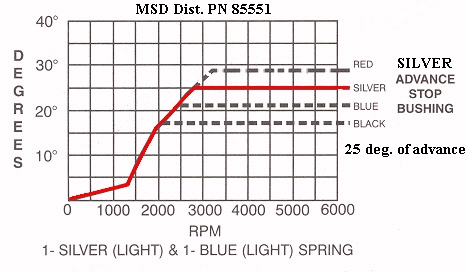
Graph courtesy of MSD
This advance curve using a MSD distributor, is easy to adjust using the silver advance bushing which allows 25 crankshaft degrees of mechanical advance, and a quick advance curve using the silver & blue advance spings provided with the distributor. The distributor also comes with “user friendly” instructions to easily alter the more conservative “factory” curve.
A rapid advance is needed – particularly with a car that is launched from idle – to help prevent hesitation (coupled with carburetor modifications) and to “hit” the torque converter hard.
This curve is also easy on the starter, requiring only 10-15 degrees of initial advance when cranking. It is critical you check the timing above 3,000 rpms – when the the distributor is fully advanced – to accurately check total timing as this advance curve begins as soon as the engine is started.
This curve also greatly improves the idle quality in a racing engine. For racing applications, there is nothing to be gained by using a vacuum advance. If octane permits, you can also try the black bushing which gives even more initial advance at the hit of the throttle!
For drag racing only applications, we recommend using the MSD 7AL-2 & MSD Pro Power coil. For street-strip applications, we recommend the MSD 6AL & MSD Blaster 2 coil installed per manufacturer’s instructions. Use recommended plug wires such as those from MSD, Taylor, etc. (not solid-core) to deliver the intensified spark to the plugs without damaging electronic components!
CAUTION: When running a 8620 roller-cam, use a bronze-alloy distributor gear to prevent destroying the soft gear on these camshafts!
Stay tuned – There’s more!
![]()
March edition – Pause for Reflection:
Being in this sport since the ’60s, I often reflect on our sport’s past compared to the present. I was recently doing research to share with you when I came across an article “Keeping Up With The Joneses” by David Reher which I feel is of significant importance today and worth your time reading.
Here’s an excerpt:
“…It doesn’t matter whether your race car arrived on an open trailer or inside an 18-wheeler. The timers don’t care whether you drove to the track in a clapped-out station wagon or flew in on a private jet. When the Christmas Tree flashes, what counts is your skill, not your stock portfolio…”
“… I respect racers who have worked hard for their success. I remember when Warren Johnson virtually lived in a bobtail truck with his wife, his race car, and his dog. I recall Funny Car crew chief Austin Coil hauling the Chi-Town Hustler around on an ancient ramp truck and winning a pair of Funny Car championships long before he hooked up with John Force’s armada. When I walk through the sportsman pits today, I’m gratified to see there are still championship-winning drivers with pickup trucks and tagalong trailers parked among the big rigs and motor coaches…”
I applaud David Reher for having the courage to write this article which is long overdue in my opinion. More and more – even in bracket racing – it seems it is more important how much pit space you can occupy and how big of tow rig you have then performance. Some of the best I can remember were people with humble beginnings that made our sport what it is today, long before the big corporate sponsors came on the scene…
Stay tuned – There’s more!
![]()
March edition – Curing the Carburetor Hesitation & Fuel Starvation on Launch:
Many experience a severe carburetor hesitation when attempting to foot brake – or “flash” – the torque converter from an idle on the starting line. Many wonder how Chris can foot-brake the Chevelle and pull the wheels on the launch without a massive backfire or hesitation.
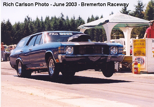
With larger duration camshafts (increased reversion) and large intake runners & ports (less velocity), this problem can seem very difficult for most to conquer, and why many have gone to a trans-brake.
Before proceeding, you must first have your centrifugal advance curve adjusted properly. Please see our discussion; Centrifugal Advance Curve & Lighting the Spark above.
Focusing now on the carburetor, try these simple solutions for Holley’s when running a single-4bbl:
1) Install a 50cc accelerator pump kit to the secondary side of your carburetor using the brown cam in the #1 position – the screw holes are marked that attach the pump cam to the throttle arm. Increase the nozzle size on the secondaries starting in the range .037 – .040. The larger the load – the heavier the car, the “tighter” the converter or taller gearing/tires – the more pump shot will be required to “mash” the throttle open without a hesitation, or backfire.
2) It is also important to note that the stock nozzle screw must be modified when increasing the nozzle size above .033. Simply file the threads flat on one side of the screw to prevent the screw itself from becoming the restriction in the circuit. The metered restriction must be the discharge nozzle itself.
3) Set the primary pump cam on the #2 setting, Increase primary nozzle size starting at .035. Again, modify the nozzle screw as indicated above. Check for proper accel. pump clearance at wide-open-throttle (WOT) between the pump arms and accelerator pump levers. You should have between .010 – .015″ of clearance which can be adjusted by the bolt thru the discharge spring on the pump arm. Check this clearance each time the fuel bowl is installed.
![]() 4) We have also seen cases of misalignment between the accelerator pump discharge hole in the fuel bowl to the metering block, and from the metering block to the carburetor body. Such misalignment will greatly limit fuel or stop discharge at the squirters! CAREFULLY chamfer the holes with a number drill and pin vise to correct this problem. And make certain the holes in the fuel bowl and metering block gaskets line up properly with these passages.
4) We have also seen cases of misalignment between the accelerator pump discharge hole in the fuel bowl to the metering block, and from the metering block to the carburetor body. Such misalignment will greatly limit fuel or stop discharge at the squirters! CAREFULLY chamfer the holes with a number drill and pin vise to correct this problem. And make certain the holes in the fuel bowl and metering block gaskets line up properly with these passages.
5) Install a modified cut float in the secondaries & install jet extensions which are now readily available. Do NOT use a power valve (PV) in the secondary side as fuel slosh to the rear will uncover the power valve – just like the jets – on a hard launch! If you are currently using a power valve in the secondaries, replace the PV with a PV plug, and increase the secondary jets by 9 sizes for starters. The PV circuit in most Holleys enriches the fuel mixture by 7 – 9 jet sizes.
6) Install a hose looping between the vent tubes to prevent fuel slosh from the primary vent tube from spilling over on the launch. ALWAYS provide a large hole in the top of the hose for proper venting of the fuel bowls! This simple “fix” also helps prevent fuel slosh from the secondary vent tube when braking hard after a long burn-out and flooding the engine. Longer vent tubes are available, but the hose trick works well and the price is right!
To review, you will need to experiment with nozzle size and pump cams to get the best launch for your application. The tips above should put you in the ballpark. Please also remember, if you replaced the secondary PV with a PV plug, you will need to monitor your fuel mixtures until best jetting is achieved.
Stay tuned – There’s more!
![]()
April edition – Fuel Supply:
For fuel supply, we use a MagnaFuel pump and regulate our fuel pressure @ 6-1/2 psi. Higher fuel pressures tend to lead to “fuel creep” – or flooding – when idling, especially when using cut or modified carburetor floats with the Holley optional large-diameter needle & seats!
Fuel pressure effects float levels. Increased pressure will raise your float level settings and richen your fuel mixture. I suggest you recheck your wet float levels when updating to a higher pressure system.
Battery voltage also effects fuel pressure. A battery in a low state of charge or failed charging system will effect fuel delivery – not to mention possible ignition misfire from a weak spark at the plugs.
Glance at your fuel pressure as you are nearing the finish line. If the pump and supply lines both to and from the pump are adequate, you should have the same fuel pressure as indicated at idle.
CAUTION: Never route fuel gauge lines (or other fuel lines) inside your driver’s compartment! Either mount the “wet” gauge outside the compartment, or use a remote sensor electronic gauge! Also be aware that in many vehicles, mounting the gauge on the cowl in front of the windshield is equally dangerous as this area is the fresh-air inlet for your air vent system.
Minumum recommended fuel lines:
#10 from fuel tank to high volume filter – such as the BG5000 – to pump inlet. Mount filter and pump below the bottom of the fuel tank or cell when possible.
#10 from outlet of pump to 1/2″ aluminum fuel line. We recommend mounting the aluminum fuel line outside the frame, especially fore and aft of flywheel area in a stick-shift application per NHRA rules.
#8 hose from 1/2″ aluminum fuel line to the pressure regulator.
#6 fuel lines from the fuel pressure regulator to carb inlet(s).
#6 fuel tank vent hose. Coil and mount vent hose or line to prevent fuel spillage or siphon in the event of a roll-over.
When using the higher volume BG400 pump a #8 fuel return line is also required, along with the larger #12 inlet hose from the tank to this pump. Follow manufacturer’s recommendations!
![]()
BG recommended fuel volumes:
Important Note: It’s essential to observe two strict rules during the volume test. One, keep a fire extinguisher handy and two, do not carry-out the test by yourself!
8 sec ————————– Under 15 seconds
9 sec ————————– Under 20 seconds
10 sec ———————— Under 25 seconds
11 sec ———————— Under 30 seconds
12 sec ———————— Under 35 seconds
Always consult your rule book whenever altering your fuel system! An oil-pressure activated switch is recommended to control electrical power to the fuel pump.
![]()
April edition – Rear-end Ratios:
“For years we thought it was optimal to gear a car to rev the engine to the RPM where it made peak HP. Then we discovered the car would go quicker if the engine was geared to run some 500-700 RPM past peak HP…”
“Why did the engine keep pulling so far beyond peak power and the car keep going quicker? Why have formula and motorcycle engine designers who have had to deal with rules that limit engine displacement attempted to raise the operating RPM of engines. For 20 years most of us have related to the engine as an air pump. Yet some of us never really understood the reason for raising the operating RPM was to increase the airflow through the engine. If the engine is MECHANICALLY STABLE, the higher you rev it, the more air will be pumped through until turbulence in the ports reduces the volume of flow…
“…We understand many dirt late model racers run 420/430 cubic inch engines geared to rev 6500-6800. Yet the 420/430 engine with the best win record is geared to run 7500 and it doesn’t have that big a camshaft. A local 355 won two unlimited Model races by gearing to run 8300-8400…”
==================
Comment: I shift the ’57 @ 7800 rpm’s and the trap rpm averages 8,300 rpm – peak HP is @ 8000 rpm’s. If you are shifting at 7200 for best et’s and your finish-line rpm is 6700, you might try using a lower rear-end gear or smaller diameter tires for best ET performance.
Many of the quickest Super Stock & Stock racers gear their cars for best ETs while sacrificing some MPH. With small-blocks in heavy cars, significant ET gains are accomplished by the 1/8-mile. Lower rear gears give engines more leverage to accelerate the vehicle.
Conversely, many in the Super categories running large-displacement engines with throttle stops for index racing gear their rides for maximum MPH.
It should also be noted that lower rear gears (or a lower 1st gear in the trans) can lead to tire-spin. However, lower gears also slows down tire rpm at a given engine RPM, thus the vehicle “recovers” sooner from tire spin then with taller gears.
Many of us running clutches desire to spin the tires approximately 2 revolutions on the launch.
Some have also improved their ETs with the use of radial slicks. The radials limit tire growth to a minimum and in effect gear the vehicle down on the top end.
Stay tuned – There’s more!
![]()
July edition – Indexing Spark Plugs:
Racing Technology – Creating the right spark: selecting, gapping, and installing spark plugs by Wayne Scraba – Courtesy of NHRA
Warning:
When indexing plugs for a small-block Chev engine with a large piston dome, the primary consideration is to prevent the piston from hitting the spark plug ground electrode! In these cases, when marking your plugs to indicate the location of the ground electrode, position that mark between 10 – 2 o’clock!
When using flat-top pistons or when piston dome to plug clearance is ample, position the ground electrode mark 180 degrees away from the center of exhaust port so the plug gap is facing the center of the exhaust valve.
Stay tuned – There’s more!
![]()
August edition – High-RPM Misfire – Suggested MSD Updates:
If you are using a MSD ignition system we strongly suggest you install the updated #8862 shielded magnetic pickup harness which connects the distributor to the ignition box. This shielded harness which includes a ground wire, greatly reduces the possiblity of induced voltage to the trigger circuit.
It is also suggested by MSD to twist the magnetic pickup wires coming out of the distributor or your pickup on your crank trigger to reduce outside voltage (RF) that can mistrigger your ignition. Install the distributor pickup harness as far away as possible from any wires, especially the primary coil wires and sparkplug wires.
We also suggest installing the MSD #8830 RF filter in the constant power supply wire and ground when using a MSD ignition box to filter any unstable voltage to your MSD Two-Step rev control or other electronic accessories.
These two inexpensive “fixes” cured a misfire gremlin that plagued us (and showed up in the tach at high rpms) when we increased the battery voltage in our ’57 Chev. We were only able to locate the problem using a lab scope to detect stray voltage near the distributor pickup wires! This common problem was also confirmed after a frustrating weekend, by the MSD tech department.
![]() Misc ignition suggestions:
Misc ignition suggestions:
1) To prevent damaging ozone buildup inside the distributor cap, we suggest drilling 1/4″ holes between the plug wire terminals on the top of the distributor cap – midway between the plug and coil wire tower – and also around the base (or remove the “points” adjusting window) where the cap mounts to the distributor for ventilation. MSD now makes such a cap for the factory-type early Chev V-8 distributor P/N 8438, an old trick we have been doing for years.
Many later-model factory distributor caps such as Ford’s Dura-Spark II have a vent incorporated in their design.
2) If you have a early model alternator using a external points-type regulator, we suggest upgrading your system to an alternator which uses an electronic regulator to reduce the amount of RF “noise” in your electrical system which can impact your electronic ignition system. It should be noted that all OEM manufacturer’s changed to electronic regulators (internal or external depending on manufacturer) when they upgraded to electronic ignitions.
![]() August ’06: Line “noise” from accessories such as a cooling fan motor or in our case, a battery cut-off switch that would go ‘open’ for a few milliseconds under vibration can cause a high-RPM misfire which will appear in your tach readings. Please read High-RPM Misfire – Suggested MSD Updates.
August ’06: Line “noise” from accessories such as a cooling fan motor or in our case, a battery cut-off switch that would go ‘open’ for a few milliseconds under vibration can cause a high-RPM misfire which will appear in your tach readings. Please read High-RPM Misfire – Suggested MSD Updates.
As we’ve learned virtually any electric component such as a bad electric water pump or cooling fan motor, fuel pump, alternator, switch or even an arcing relay can cause a high RPM misfire with the 7AL-2 which shows up on your tach. Even with the MSD #8830 RF filter installed in the constant power circuit, voltage spikes can enter the ignition box thru the unfiltered ignition switched power to the 7AL-2.
At this time, you must eliminate one component at a time to isolate the culprit.
Stay tuned – There’s more!
![]()
February ’05 edition – Important Assembly Tips:
How to Degree Your Camshaft – PDF file courtesy of Comp Cams [Our preferred intake lobe-center method]
How To Verify Proper Valve Train Geometry – Lunati cams
?t=2m
Pushrod Clearance:
You’ve undoubtedly heard or read about checking for valve spring coil bind at max. lift, retainer to valve guide or seal clearance, valve to piston clearance, and piston to head clearance [see Comp Cams PDF file above]. However, due to the many different head manufacturers and rocker arms and ratios available for the small-block Chev there is another area you need to check for mechanical interference that you seldom read about.
BEFORE your torque your heads on your engine and crush those expensive head gaskets there is another area that requires close scrutiny. Pushrod to pushrod hole clearance!
Place the heads on your block with head gaskets and just snug all your head bolts. Install your pushrods, lash caps and the rockers you are going to use (we recommend checking one cylinder at a time). Set your valve clearance at zero lash. Note if the pushrod is touching the pushrod hole in your heads. (If the pushrod is touching the head, the tip of the pushrod will not seat in the cup on your rocker arm properly and destroy both the rocker cup and pushrod) Slowly turn the engine over by hand noticing the pushrod clearance especially at max. lift. If you have adequate clearance in all your pushrod holes then proceed with torquing your heads. If not you can grind or have your pushrod holes machined for adequate clearance before destroying your new head gaskets or worse!
Valve Guide Clearance:
Before you bolt those after-market assembled heads on your race engine, make certain to have a good machinist check your valve guide clearance! Recently a several fellow racers stuck valves open hitting the pistons on his first pass even with with high-tension roller valve springs because of lack of valve guide to stem clearance! (The engine had more than adequate valve to piston clearance). Even the remaining valve stems were badly galled. These heads came asembled by the manufacturer with the factory cast guides. Personally we recommend having bronze guides installed on all race applications!
Also have the valve spring pressures checked. It has been our experience that the pressures on the roller-springs installed on the after-market heads leaves much to be desired for drag race applications. For 8620 billet roller camshafts designed for drag racing using solid roller lifters you want at least 240 lbs. of seat pressure with a minimum of 650 lbs. open! And to handle these spring pressures severe-duty stainless steel valves, lash caps, titanium retainers, machined 10-degree keepers, and reputable chrome-moly pushrods must be used!
Also make certain to use a bronze alloy distributor gear – we have found those manufactured by MSD to be the best – when using a 8620 cam and some kind of camshaft thrust button in conjunction with a torrington bearing to prevent block wear must also be used to prevent excessive cam walk when using any roller camshaft! Also a reputable gear drive or belt drive is highly recommended with roller cams as timing chains will stretch and can fail due to the higher loading on the valve train.
CAUTION: For hydraulic-roller applications – which are often not 8620 billet grinds – consult your camshaft manufacturer for recommended valve spring pressures! The spring pressures mentioned above will destroy the lifters and camshaft! Hydraulic-roller cams usually only require approx. 135 lbs of seat pressure with a maximum open pressure of 330 lbs.
While the flow figures of today’s after-market heads and durablilty are usually very good, the assembled heads may not be your best bet in the long run!
Camshaft Lobe to Rod Clearance:
Small-block Chevs using aluminum rods and a roller camshaft most often require a “small base-circle” (smaller diameter) camshaft to provide adequate cam lobe-to-rod clearance! This if often true with stroker engines using steel rods. When switching to a small base-circle camshaft be certain to check your pushrods for proper length to preserve proper valve train geometry.
=========================
Flat-tappet Camshaft Tip
For those running a 350 c.i. – 400 Chev engine looking for a LOT of torque at a reasonable price, we recommend the following Competition Cams flat-tappet grind:
P/N: 12-611-5 Grind Number: CS290B-6
Use 1.6:1 rockers!
Recommended Stall: 4,000 rpm in heavy car.
Lift: .540″ Int: (.576″ w/1.6 rockers) — Exh: .534″ (.569″ w/1.6 rockers)
Duration @ .050″ — Int: 255 deg. — Exh: 266 deg.
Gross Duration — Int: 290 deg. — Exh: 304 deg.
Cam Timing: 104 degrees (2 deg. advanced)
This is a grind that we used years back with great success. Break-in the cam and lifters at suggested manufacturer spring pressures. Recommend higher spring pressures to 130# on the seat, approx. 330# open ONLY AFTER approximately 20 runs at manufacturer recommended pressures!
CAUTION: Higher valve spring pressures will destroy the cam lobes and/or lifters if used initially! Please note: Higher then recommended spring pressures voids any warranty. Recommend titanium valve spring retainers w/10 degree locks!
Stay tuned – There’s more! – Roger
![]()
February ’05 edition – Pro Stock Staging & Leave by Jeg Coughlin, Jr:
Jeg Coughlin, Jr.
“After crewmembers help me back up, I pull forward and stop about a car length before the staging beams to check the gauges and make sure that the transmission is in low. After the pre-stage bulb is lit, I set the front-brake pressure at 300 pounds and hold it with the line-loc. With the line-loc activated, the car won’t roll, so I use my left foot for the clutch and right for the gas pedal to stage. I rev the engine to about 4,000 rpm and slowly release the clutch to move forward. When both cars are staged, I floor the gas pedal and the engine goes right up to the MSD chip, which holds it at a predetermined setting between 6,000 & 7,000 rpm, depending on the tune-up. Once I see anything [on the Tree], I let out the clutch, and I’m off” – Source: NHRA 2005 Fan Guide
Comment: Some have said Pro-Stocks are leaving at 8,000 rpm. This never made any sense to me since they use a centrifugal assisted clutch. [If they left at 8,000 rpms, the clutch would be totally locked-up, negating the advantage of a centrifugal assisted clutch!] What they are seeing is the engine instantly reving to 8,000 rpms when the line-loc is released and the clutch locking up at around 8,000 rpms depending on the clutch setting and traction conditions.
Our clutch is not centrifugal assisted, so we leave between 7,400 to 8,000 rpms with the ’57 depending on track conditions taking into consideration our engine tune-up and static clutch pressure.
![]()
August ’05 edition – Rod Length Relationships by Stahl Headers
Comment: We’ve found a stock-length, 5.7″ rod works well in a 283, a 6.0″ rod in a 327-350, a 5.7″ or 6.0″ rod in a Chev small-block 400 (clearances permitting).
In general, a shorter rod improves bottom-end torque, a longer rod improves top-end torque and puts less stress on engine components – in particular pistons, wrist pins, rods & cylinder walls.
For those not familiar with engine building, remember when increasing your stock rod length an appropriate piston with the correct pin & ring placement must also be used!
![]()
November ’05 edition – Rocker Ratios:
Increasing your rocker ratio will give your engine a boost if the current camshaft is too small for optimum performance. In effect, the higher rocker ratio increases the lift at the valve of the camshaft you are currently running. For example, with a small-block Chev with a valve lift of .600″ with a 1.5 ratio rocker, by switching to a 1.6 rocker the lift at the valve would be .640″ of lift. With a big-block running a 1.7 rocker with the .600 lift, switching to a 1.8 ratio rocker would increase the valve lift to .635″
CAUTION: Of course when changing to a higher ratio rocker, remember that clearances become an issue! Clearances such as valve-to-piston, valve spring retainer-to-guide & coil bind must be adequate to run the higher ratio rocker! Also remember that since you are opening the valve further, valve spring tension and opening and closing velocities will increase with the higher lift thus increasing the stress on the entire valve train including valves, retainers, keepers, springs, pushrods, timing chain/belt/gears and camshaft.
Higher rocker ratios also impact valve train geometry. You may well find that when installing a higher ratio rocker that a shorter pushrod is often required to maintain proper valve train geometry.
How To Verify Proper Valve Train Geometry – Lunati cams
Please also see video below for checking for correct pushrod length:
?t=2m
And remember, if your current camshaft profile is adequate with the stock ratio rockers, using higher rocker ratios can decrease the torque in the engine hurting performance. And some cam profiles will show improvement using the higher ratio rockers only on the intake or exhaust valves, but not both! There is no magic formula!
![]()
February ’06 Edition – Holley 750 main body upgrade:
Holley has announced a new HP Main body retro-fit kit for 4777, 4778, and 4779 list numbers. Holley states the following:
– Converts 0-4777 (650 cfm), 0-4778 (700 cfm) and 0-4779 (750 cfm) shiny or dichromate Holley Double Pumper® carbs to a 750 cfm HP Main body for increased horsepower, torque and airflow.
– Reduces turbulence and smoothes air entry into the venturi.
– Pre-calibrated for optimum performance and drivability on a wide variety of applications.
P/N 134-300C HP Main Body Retrofit kit (dichromate)
P/N 134-300S HP Main Body Retrofit kit (shiny)
A picture of the main body kit shows a chokeless design (no primary air horn), contoured airhorn entry, down-leg boosters and screw-in air bleeds.
See Holley picture and technical information, courtesy of Holley Performance®
![]()
May ’06 Edition – Holley Nitrous Oxide Technical Article:
Holley Performance has an excellent technical support article for those of you interested in using the bottle. The article is available in a PDF file located at:
1) An engine requires wider ring-end gaps when running the bottle.
2) Get the engine tuned properly on gas before using the bottle.
3) Retard the spark as recommended by Holley when you activate the bottle with an electronic spark retard to prevent detonation.
4) Colder heat-range plugs are often required when running the bottle to also prevent detonation. Do not run projected-tip sparkplugs when using nitrous oxide. The long ground strap will overheat and melt!
5) Some head, piston & camshaft combinations that produce excellent horsepower on gasoline do not respond well or last long with nitrous oxide.
6) Using nitrous oxide adds additional stress to any engine!
7) The plate systems with the spray-bars under the carburetor are well designed and researched. Use the suggested matching spray bars to maintain proper fuel mixtures.
8) Start out with small shots and slowly work your way up!
9) Follow all manufacturer instructions and recommendations making certain you have an adequate fuel supply of the required octane rating to the fuel solenoid at all times!
10) If the nitrous oxide solenoid opens (or sticks open) without additional fuel enrichment, bad things are going to happen!
NOS Nitrous Oxide Systems courtesy of Holley Performance®
We do NOT use nitrous oxide on our race cars, nor are we an advocate of running nitrous oxide. We provide the above links for those who desire to do so at their own risk.
![]()
May ’06 Edition – Chassis Basics:
Competition Engineering : Tech Articles
Understanding the Basics of Chassis, Suspension and Traction Equipment – Torco’s Racing Fuel Competition Plus.com
E&Y comment: It is highly desirable to be able to adjust your chassis, such as shock rates (at least extension or “rebound”), spring rates (coil overs), front end travel, preload, etc. to launch straight and tune the chassis for varying track conditions.
We also recommend if you are going to use wheelie bars on a heavy car, to use adjustable spring-loaded bars on those applications. You need the springs to provide additional control and adjustability to prevent unloading the tires on the launch. For those applications, we recommend the wheelie bar made by Chassis Engineering, C/E3618.
Here’s two additional excellent articles provided by Chris Alston in PDF format:
http://www.cachassisworks.com/Stories/TechCAC-003_WEB.pdf
http://www.cachassisworks.com/Stories/TechVAS-001_WEB.pdf
![]()
September ’06 Edition – Breaking the Big MPH Myth:
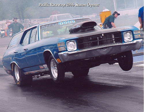
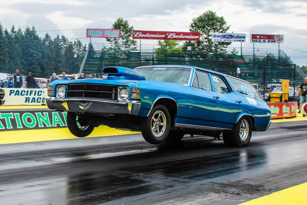
Edwards & Young ’71 Chevelle wagon
Consistency begins right here on the starting line getting the power to the ground
Jeff Dykes Photo
Many fellow racers thought we had gone batty to run our small-block ’71 Chevelle wagon in Super Pro this past year stating the need for high MPH to succeed in the Super categories. That’s the myth anyway.
Yes, there is an advantage to having the quicker car in bracket racing. The slower car that always leaves first has the first opportunity to red light (foul). But let’s be realistic, there is no way we can make a heavy door car with a small-block run 175 MPH. Even if possible it certainly would not be practical.
The trend in the past years has been to run increasingly larger displacement engines that are now available in a light chassis to have the big MPH as you approach the finish line to judge your opponent as you catch them. The reality is a dragster running 175 MPH catching our 120 MPH wagon cannot judge the closing distance any better than we can judge them!
Our wagon is one of the slowest cars in Super Pro yet we had great success against the very well prepared and much quicker and faster dragsters this past season. We were successful because Chris cut excellent lights, the combination in our Chevelle was very consistent and most importantly, predictable, and Paul picked excellent dial-ins from the data we have collected over a broad range of atmospheric and track conditions.
Bracket racing still comes down to cutting a competitive light and running your number, regardless if that number is a number you pick as your dial-in or an E.T. dictated by the category you run such as 10.90 (Super Street), 9.90 (Super Gas) or 8.90 (Super Comp). All are a form of bracket racing which has become very competitive in the past few years as the equipment and drivers have markedly improved. We have proved if you run your race you can be competitive without the big MPH.
![]()
The A, B, C’s of EGT’s and Oxygen Sensors by Pro Systems Carburetors – Posted Feb 08
“…EGTs and Oxygen sensors are tools that can lie to you, but they’re great for educating you on what to look for, so pull that header off or pull out that sparkplug when the car is running good. Get a good look and remember what you see. Sparkplugs and header pipes are harder to read but they rarely tell a lie.”
Related articles:
Reading Exhaust Valves & Ports – Feb 04 – Edwards & Young
![]()
Quench Quest: Squish, Quench, and Piston-to-Head Clearance By Jeff Smith – Posted 30 Apr 08
![]()
October, November ’08 Edition – CFM Head Flow Discussion:
Bigger is Not Always Better – Cylinder head tech from a specialist By Darin Morgan – Posted 17 Oct 08
“…So it can be said that the most important rules regarding the induction system design are: Velocity, Velocity, Shape, Velocity and last but not least, Air Flow.
“Velocity is the life of power! Without the correct air velocity, you can have all the flow in the world and the engine won’t make a lick of power. Air speed within the induction system is the most powerful tuning instrument in the head porter’s arsenal…”
Related article:
The Great Balancing Act & Flow Bench Fallacies – Feb 04 – Updated May 08
![]()
November ’09 Edition – Dominator Air Bleed Locations:
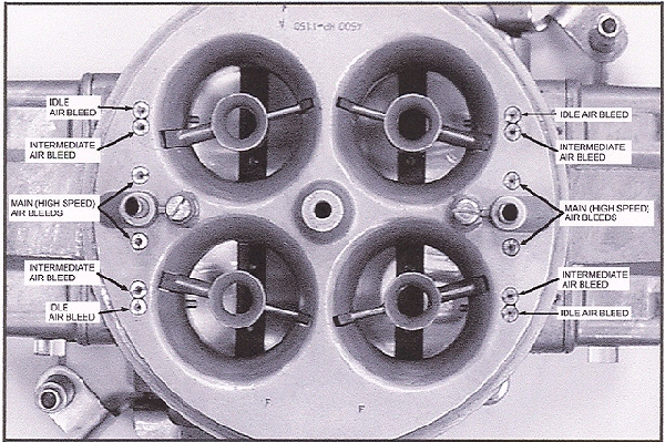
Courtesy of Holley® Carburetors
![]()
December ’09 Edition – Wider 2nd Ring End Gaps:
Speed-Pro now has a new recommendation for the 2nd ring. They suggest to widen the ring end gap from our usual .017 to .023″ which reportedly improves the sealing of the upper ring. I’ve read other reports on this over the past year which have suggested the same recommendation which I will follow. This is also why some newer pistons offer the “compensation” groove between the top and 2nd ring which our older pistons don’t have. The top ring-end gap recommendation remains the same as our last set, .020″ Of course the bigger the bore, the wider ring end gaps required. Follow manufacturer recommendations for YOUR engine!
Here’s what Speed-Pro states in the ring instructions:
“Most of the 2nd ring gap recommendations are larger than the top rings. Recent testing has proven that a larger 2nd gap increases the top ring’s ability to seal combustion. This larger ‘escape’ path prevents inter-ring pressure from building up and lifting the top ring off the piston.”
![]()
Oil Pump Volume and Pressure Explanation – by Melling Engine Parts:
![]()
Are Burnouts Abusing Your Engine? by David Reher – Posted December 17, 2010
![]()
Debunking Aluminum Rod Myths With GRP – DragZine.com – October 25, 2011
![]()
Testing Lunati Cams – 4/7 Swap Cam Test – Hot Rod – Posted January 6, 2012
![]()
Melling Oil Pump Relief Springs – Posted August 24, 2012
![]()
Rolling ‘EZ’ with ISKY Cams – Drag Racing Online – Posted September 27, 2012
![]()
Are your valve springs and pushrods ready for next season? – Drag Racing Online – Posted April 4, 2013
![]()
Use a simple 10-second check and avoid three common valve-lock troubles in racing engines – Drag Racing Online – Posted July 29, 2013
![]()
Camshaft 101: The History And Substance Of Camshafts by Bobby Kimbrough – Posted December 30, 2014
![]()
Electronic Diagnostics – January 2016 by Roger Young
![]()
We’ve had very good results breaking our engines in on Rotella T 15W-40 oil. It is very high in zinc and seats the new rings well. After about 15 runs we change to Brad-Penn 20W-50 or the Lucas oil.
![]()
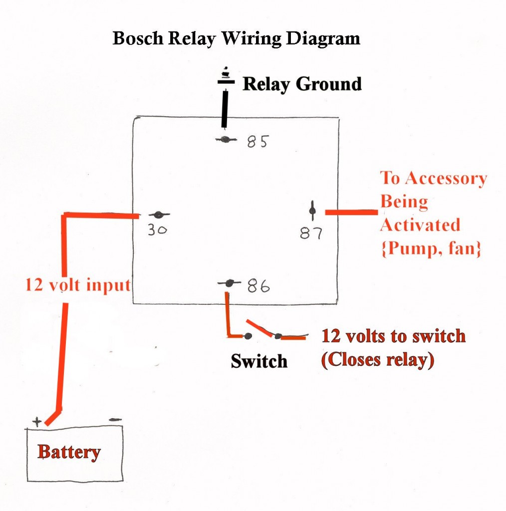
We’ve been asked about wiring Bosch relays, here’s a wiring diagram looking at the bottom of the relay:
![]()
David Reher: Oil Is Everything – Posted September 2016
“Controlling the supply of oil in the shutdown area should be a top priority.” by David Reher, Reher-Morrison Racing Engines – Posted October 2017
![]()
![]()
Lengthy discussion, instructions & video on our new Ram clutch for 2018 – Posted August 1, 2017
![]()
What Is A Strutted Piston – Wiseco Automotive – March 2018
![]()
![]()
Standard Ring Tension Is A Myth – Wiseco Pistons – October 2018
![]()
Pedal ratio calculator, Gear ratio and RPM calculator, Tire size calculator courtesy of Mark Williams Enterprises, Inc. – January 2019
![]()
How to pick valve springs for your race car – NHRA – May 10, 2019
Pretty good article. It has been my personal experience that many of the valve springs that come in a cam kit are too light for high RPM engines with mechanical roller cams. We’re having good luck with the PacAloy springs in our engines – Roger Young
![]()
The Importance Of Clutch Break In Explained – Ram Clutches – Oct 29, 2020
![]()
Questions, comments, additional articles you would like discussed?
E-mail Roger Young @ roger@northwestvets.com, Subject: Tech Tips
About the author: Roger has mechanical training in civilian aviation and while serving with the U.S. Army during the Vietnam war was a helicopter crew chief, promoted to Line Chief, and Periodic Inspection team leader. He specialized on the OH-6A Cayuse, OH-58 Kiowas, and AH-1G Cobra gunships.
Upon his departure from the Army he returned to the automotive field and specialized in engine diagnostics, tune-ups, and drivability issues with the advent of computer-controlled vehicles and was an ASE certified mechanic. He has over 36-years of experience in the field working on many makes and models.
He began racing in the late ’60s and entered the Modified Production ranks in the 70s. He is currently retired and resides with his beloved wife, Pam, in the Seattle area.
![]()
Edwards & Young Archives
Features archived post-race reports, construction details of our Chevelle, and more pics…




















Howdy would you mind letting me know which hosting company
you’re utilizing? I’ve loaded your blog in 3 different
internet browsers and I must say this blog loads a lot faster then most.
Can you suggest a good hosting provider at a reasonable price?
Cheers, I appreciate it!:
\
Yahoo hosted our blog for years, currently it is HostGator!